| Items |
 /Asset/finlineseries.jpg /Asset/finlineseries.jpg 1/2FR---BRT 1/4 Inch (in) Port Size, Tubular Stainless Steel FR Series Automatic Control Valve |
 /Asset/finlineseries.jpg /Asset/finlineseries.jpg 3/4FR---BRB 1/4 Inch (in) Port Size, Bronze FR Series Automatic Control Valve |
 /Asset/finlineseries.jpg /Asset/finlineseries.jpg 3/4FR---BRS 1/4 Inch (in) Port Size, Stainless Steel FR Series Automatic Control Valve |
 /Asset/finlineseries.jpg /Asset/finlineseries.jpg 3/4FR---CRB 3/8 Inch (in) Port Size, Bronze FR Series Automatic Control Valve |
 /Asset/finlineseries.jpg /Asset/finlineseries.jpg 3/4FR---CRS 3/8 Inch (in) Port Size, Stainless Steel FR Series Automatic Control Valve |
|||||
| Description |
N/A
The reverse-acting FR/FGR series valve is an inexpensive way to maintain optimum discharge temperatures for more efficient and economical use of your cooling media. Because of its reverse action design, the valve closes when fluid temperature drops below a preset temperature — effectively eliminating the inefficient discharge of low temperature cooling fluid.Controlled leakage* can be provided through the valve for constant, true temperature monitoring. The FR/FGR series valve is an economical way to maintain optimum operating temperature of equipment for maximum efficiency. Note: Specify temperature between 35° and 255°F in 5°F increments. Differential from full open to full closed is typically 10° to 15°F. Valve opens/closes gradually. 
|
|||||||||
| NPT Thread Size | N/A 1/2 in | N/A 3/4 in | N/A 3/4 in | N/A 3/4 in | N/A 3/4 in | |||||
| Valve Type | N/A FR Series Automatic Control Valve | |||||||||
| Port Size | N/A 1/4 in | N/A 1/4 in | N/A 1/4 in | N/A 3/8 in | N/A 3/8 in | |||||
| Maximum Operating Pressure | N/A 200 psig | N/A 200 psig | N/A 200 psig | N/A 80 psig | N/A 80 psig | |||||
| Flow Coefficient (Cv) | N/A 0.5 | N/A 0.5 | N/A 0.5 | N/A 0.9 | N/A 0.9 | |||||
|
Valve Action |
N/A Reverse | |||||||||
| Body Material | N/A Tubular Stainless Steel | N/A Bronze | N/A Stainless Steel | N/A Bronze | N/A Stainless Steel | |||||
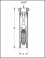
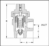
| Dimensional Drawing |
N/A
 FR/FGR Schematic Figure 1 |
N/A
 FR/FGR Schematic Figure 2 |
N/A
 FR/FGR Schematic Figure 2 |
N/A
 FR/FGR Schematic Figure 2 |
N/A
 FR/FGR Schematic Figure 2 |
|||||
| Dimension A1 | N/A 1-1/8 in | N/A 1-7/8 in | N/A 1-7/8 in | N/A 1-7/8 in | N/A 1-7/8 in | |||||
| Dimension B2 | N/A 5-1/4 in | N/A 4-3/4 in | N/A 4-3/4 in | N/A 4-3/4 in | N/A 4-3/4 in | |||||
| Dimension C3 | N/A | N/A 1-7/8 in | N/A 1-7/8 in | N/A 1-7/8 in | N/A 1-7/8 in | |||||
| Net Weight | N/A 3/4 lb | N/A 2-3/4 lb | N/A 2-3/4 lb | N/A 2-3/4 lb | N/A 2-3/4 lb | |||||
| Typical Applications | N/A Any other application requiring removal of heat with any circulating fluid compatible with bronze or stainless steel Compressor Cooling Water Cooling Drums or Rolls Engine Cooling Water Heat Exchangers Platens Scald protection for emergency safety shower | |||||||||
| The Ogontz Guarantee | N/A We will repair or replace on a no-charge basis, FOB Willow Grove, PA, any valves or traps returned to us within 18 months, if found to be defective in material or workmanship. | |||||||||
| Full Open Set Point Temperature | N/A 45 ºF50 ºF55 ºF60 ºF65 ºF70 ºF75 ºF80 ºF85 ºF90 ºF95 ºF100 ºF105 ºF110 ºF115 ºF120 ºF125 ºF130 ºF135 ºF140 ºF145 ºF150 ºF155 ºF160 ºF165 ºF170 ºF175 ºF180 ºF185 ºF190 ºF195 ºF200 ºF205 ºF210 ºF215 ºF220 ºF225 ºF230 ºF235 ºF240 ºF245 ºF250 ºF255 ºF | |||||||||
| Plug Material | N/A PTFE Silicone | |||||||||
| Optional Standard Leak Ports | N/A LX - 1/4 to 1/2 GPM at 60 PSIG LZ - 1/2 to 1 GPM at 60 PSIG | |||||||||
|
||||||||||


